LUUM.IO
XPD-T4H-G - DATA SHEET#
Product Overview#
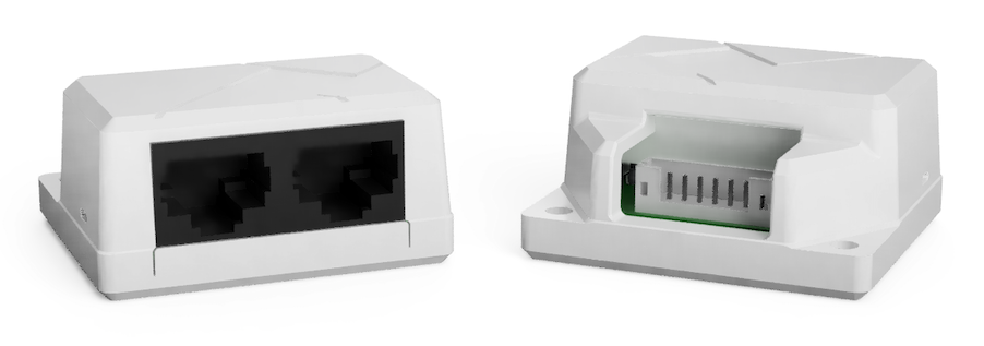
The X-PoE powered device serves as an intermediary between the X-PoE port and the connected LED lights or other devices, enabling power transmission and providing support for high power outputs. The PD takes two RJ45 connections from X-PoE ports and converts them to four separate channels, each with a pair of positive (+) and negative (-) conductors. These channels are used for powering LEDs, such as an RGBW strip, or other compatible devices. The PD is capable of providing a total power output of up to 260W1.
Confirm PD Configuration
The PDs can be utilized in both generic and customized configurations, tailored to accommodate specific load types. It is crucial to verify and install the appropriate PD before establishing a connection with an X-PoE lighting controller.
Specifications#
| XPD-P2H-G SPECIFICATIONS | |
|---|---|
| Dimensions | 45.5 mm x 22.3 mm x 40.7 mm (1.8 in x 0.9 in x 1.6 in) |
| Weight | 0.03 kg (0.07 lbs) |
| Interfaces | (2) RJ45 X-PoE Input Ports (4) Individually Controlled X-PoE Lighting LED +/- Terminal Pairs2 |
| Power Input | 48VDC to 57VDC Input From X-PoE Port3 |
| Maximum Power Consumption | 260W (at 57VDC) With Both Channels Fully Loaded At 100%4 |
| Environment | Operating Temp: -20°C to +35°C (-4°F to 95°F) Storage Temp: -20°C to +50°C (-4°F to +122°F) Humidity: 10% to 90% (non-condensing) |
| Certifications | ETL, Plenum *Pending |
| Warranty | 5 Years |
Maximum Power Output
Maximum output power is dependant upon the input voltage and the forward voltage of the connected light engine.
Front Panel#
The XPD-T4H-G front panel is shown below:
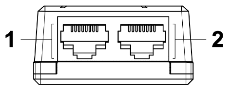
- X-PoE Power Input
- X-PoE Power Input
Warning
This PD is meant to have two X-PoE inputs. The second RJ45 port is not for daisy chaining.
Rear Panel#
The XPD-P2H-G rear panel is shown below:
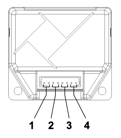
- Channel 1 Output (+ / -), RED when configured for RGBW control
- Channel 2 Output (+ / -), GREEN when configured for RGBW control
- Channel 3 Output (+ / -), BLUE when configured for RGBW control
- Channel 4 Output (+ / -), WHITE when configured for RGBW control
Connector
The LED lighting loads are connected via a JST PHR-8 connector.
-
2 ports, maximum 130W per port with a 57V input, see D1.2 - Output Power Range. ↩
-
2 ports, 2 channels per port, 67W per channel with a 57V input. ↩
-
PD must be powered by an X-PoE lighting controller. ↩
-
X-PoE port must be configured properly. ↩