LUUM.IO
XS-108H - INSTALL GUIDE#

Introduction#
About This Guide#
This comprehensive guide offers detailed instructions for the seamless installation and optimal configuration of your XS-100 series lighting controller. In addition to the step-by-step installation process, this guide provides invaluable insights into essential mounting techniques, crucial safety requirements, and concise troubleshooting procedures, whether you are integrating the lighting controller into a rack system or utilizing it as a standalone device.
Cautions And Warnings#
When installing hardware, it is important to follow safety precautions to avoid potential injuries or damage to the equipment. Failure to follow safety guidelines can result in electric shock, fire, or other hazards.
DEFINITIONS:
Note
A note is typically used to provide additional information or clarification that is relevant to the installation process. It may include recommendations, tips, or other useful information that can help ensure a successful installation.
Caution
A caution statement indicates a potential hazard that could result in minor or moderate injury, or cause damage to the product if appropriate precautions are not taken. They are used to alert the reader to a potential risk and provide instructions on how to avoid it.
Danger
A danger statement indicates a potential hazard that could result in serious injury or death if appropriate precautions are not taken. They are used to alert the reader to a potential risk that is critical and requires immediate attention to prevent harm. It may provide instructions on how to avoid the hazard or recommend seeking professional assistance.
SAFETY PRECAUTIONS:
Danger
Do not connect the device to an external power supply before installing. Failure to observe this warning may result in electrical shock or death.
Danger
Turn the external power supply off and ensure the unit is disconnected from the external power supply before performing any maintenance. Failure to observe this warning may result in electrical shock or death.
Danger
When connecting a device to power, it is important to properly secure wires in screw terminals to prevent the risk of electrical shock or fire. Failure to do so could result in damage to the equipment, injury, or death.
Danger
Always use the proper gauge wire for the external power supply being used. Using an incorrect gauge wire can result in overheating, electrical fires, or other dangerous situations.
Danger
When installing the device, read the mounting instructions carefully and always use the correct mounting hardware. Using incorrect hardware or improperly installing the hardware can result in the equipment falling or shifting.
Caution
Ensure that the unit does not overload the power supply. Add the maximum power consumption of all the devices connected to the unit, and compare that total with the rated wattage of the power supply.
Caution
Equipment is for indoor use only.
Caution
Make sure airflow around the unit is not restricted.
Caution
Disassembling any part of the unit voids the warranty and regulatory certifications. There are no user-serviceable parts inside the unit.
Caution
Do not install the unit in an environment where the operating ambient temperature might exceed 40ºC (104ºF).
Caution
This equipment is not suitable for use in locations where children are likely to be present.
Note
The unit is an indoor device. If it will be connected to outdoor devices or lighting loads, an arrester must be installed on the cable between outdoor devices/loads and the unit.
Lors de l'installation de matériel, il est important de suivre les précautions de sécurité afin d'éviter tout risque de blessure ou de dommage matériel. Ne pas respecter les consignes de sécurité peut entraîner des risques de choc électrique, d'incendie ou d'autres dangers.
DÉFINITIONS:
Remarque
Une remarque est généralement utilisée pour fournir des informations supplémentaires ou des éclaircissements pertinents par rapport au processus d'installation. Elle peut contenir des recommandations, des conseils ou d'autres informations utiles qui peuvent aider à assurer une installation réussie.
Attention
Une mention d'attention indique un danger potentiel qui pourrait entraîner des blessures légères ou modérées, ou endommager le produit si les précautions appropriées ne sont pas prises. Elles sont utilisées pour alerter le lecteur d'un risque potentiel et fournir des instructions sur la manière de l'éviter.
Danger
Une mention de danger indique un danger potentiel qui pourrait entraîner des blessures graves ou la mort si les précautions appropriées ne sont pas prises. Elles sont utilisées pour alerter le lecteur d'un risque potentiel critique et nécessitant une attention immédiate pour éviter tout dommage. Elles peuvent fournir des instructions sur la manière d'éviter le danger ou recommander de faire appel à une assistance professionnelle.
PRÉCAUTIONS DE SÉCURITÉ:
Danger
Ne connectez pas l'appareil à une source d'alimentation externe avant l'installation. Ne pas respecter cet avertissement peut entraîner un choc électrique ou la mort.
Danger
Éteignez l'alimentation externe et assurez-vous que l'appareil est déconnecté de l'alimentation externe avant d'effectuer toute maintenance. Ne pas respecter cet avertissement peut entraîner un choc électrique ou la mort.
Danger
Lors de la connexion d'un appareil à une source d'alimentation, il est important de fixer correctement les fils dans les bornes à vis afin de prévenir les risques de choc électrique ou d'incendie. Ne pas le faire peut entraîner des dommages matériels, des blessures ou la mort.
Danger
Utilisez toujours le calibre de fil approprié pour l'alimentation externe utilisée. L'utilisation d'un calibre de fil incorrect peut entraîner une surchauffe, des incendies électriques ou d'autres situations dangereuses.
Danger
Lors de l'installation de l'appareil, lisez attentivement les instructions de montage et utilisez toujours le matériel de montage correct. L'utilisation d'un matériel incorrect ou une installation incorrecte peut entraîner une chute ou un déplacement de l'équipement.
Attention
Assurez-vous que l'unité ne surcharge pas l'alimentation électrique. Additionnez la consommation d'énergie maximale de tous les appareils connectés à l'unité et comparez ce total à la puissance nominale de l'alimentation électrique.
Attention
L'équipement est destiné à une utilisation à l’intérieur uniquement.
Attention
Assurez-vous que la circulation de l'air autour de l'unité n'est pas entravée.
Attention
Le démontage de toute partie de l'unité annule la garantie et les certifications réglementaires. Il n'y a pas de pièces réparables par l'utilisateur à l'intérieur de l'unité.
Attention
N'installez pas l'unité dans un environnement où la température ambiante de fonctionnement pourrait dépasser 40ºC (104ºF).
Attention
Cet équipement n'est pas adapté à une utilisation dans des endroits où des enfants sont susceptibles d'être présents.
Remarque
L'unité est un dispositif d'intérieur. Si elle est connectée à des dispositifs extérieurs ou à des charges d'éclairage, un parafoudre doit être installé sur le câble entre les dispositifs extérieurs et l'unité.
Product Overview#
The XS-108H lighting controller represents a cutting-edge, high-performance solution, offering multiple channels for remote constant current/voltage LED driving. This controller stands out by providing 8 ports that can deliver controlled power in either IEEE standard (90W per port) or X-PoE (130W per port)1 configurations. Powered by a 48V-57V low-voltage DC input2, it ensures efficient and reliable operation within the lighting system, maintaining consistent and optimized power supply to the connected LED fixtures. With its advanced features and robust design, the XS-108H lighting controller sets the stage for exceptional performance and flexibility in contemporary lighting applications.
- 8 auto-sensing lighting control ports for use with IEEE devices or X-PoE loads.
- All ports backwards compatible with IEEE802.3af/at/bt-type 4 support up to 90W/Port.
- 2 individually controllable channels up to 65W on each port1.
- Tunable white support for human centric lighting up to 2x65W.
- Constant current dimming up to 2300/Port (1150/Channel), down to 1%.
- Constant voltage dimming from 24V up to input voltage (48-57V depending on supply).
- Individual power monitoring for every channel.
- Limited autonomous load detection and failure detection.
- Power metering on all ports with >95% accuracy.
- REST API and MQTT lighting controls interface.
- Embedded web app for load configuration.
- DHCP and Static IP support for light management.
- 48V-57 VDC input with locking connector2.
- Override dry contact closure for emergency operation.
- Native 1U half-rack width form factor, able to wall/ceiling mount standalone.
- 2 units joinable to form a full 1U lighting controller.
- Indicator LEDs and buttons for operation/troubleshooting:
- 1 green/red LED to indicate valid system power (on back).
- 1 multi-color LED to indicate the system status.
- 8 multi-color LEDs to indicate port status.
- 1 reset button for troubleshooting/factory reset.
- 1 programming override button for operation during a loss of communication.
Note
Maximum output power is dependant upon the following things:
- Input voltage
- Forward voltage of the connected light engine
Ordering Information#
| CONTROLLERS | |
|---|---|
| XS-108H | 8 port (16 channel) lighting controller |
| ACCESSORIES | |
|---|---|
| XS-KIT-LB | Full-width rack mounting kit for individual unit |
| XPD-P2H-G | Generic 2ch Cable Adapter w. Pass Through for connecting LED’s/Fixtures |
| XPD-T2P-G | Generic Panel Mount 2ch Cable Adapter for connecting LED’s/Fixtures |
Installation#
Parts List#
Before getting started with the installation process, it's important to make sure all the necessary components are included. Here's what should be found inside the box:
- (1) X-PoE Lighting Controller/Network Switch
- (1) Screw Terminal Power Connector
- (1) Screw Terminal Input Connector
- (2) Rack/Wall Mounting Bracket
- (8) M3 Bracket Screws
- (2) Device Coupling Bracket
- (8) M3 Bracket Screws
- (4) 10/32 Rack Screws
- (10) RJ45 Dust Plugs
Included in each kit are all the necessary hardware to securely mount two devices side-by-side in 1U of an equipment rack. However, if you intend to mount a single device in 1U of an equipment rack, you will require an additional bracket. The XS-KIT-LB is available for purchase separately and contains the required hardware to properly mount a single device in a rack:
- (1) Long Rack Mounting Bracket
- (4) M3 Bracket Screws
- (2) 10/32 Rack Screws
Please ensure all items are accounted for. If any item is missing or damaged, contact the place of purchase for a replacement.
Stand-Alone Installation#
Note
The hardware devices shown in these instructions are meant for guidance purposes and may not accurately represent the specific device or environment you're installing into.
Perform the following steps to install the device on a shelf or table:
- Review all cautions and warnings to ensure safe installation practices are followed.
-
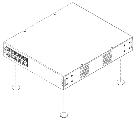
Attach (4) adhesive rubber feet (not included) to the underside of the device (fig. 1).
FIG. 1: Attaching the rubber feet
-
Ensure the unit is placed on a sturdy and flat surface, and that the ventilation holes are not obstructed.
Wall/Ceiling Mount Installation (single unit)#
Note
The hardware devices shown in these instructions are meant for guidance purposes and may not accurately represent the specific device or environment you're installing into.
Perform the following steps to install the device in on a wall or ceiling:
- Review all cautions and warnings to ensure safe installation practices are followed.
-
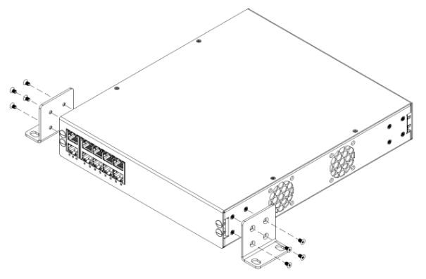
Attach the rack/wall mounting brackets to both sides of the device using the provided M3 screws, and that the rack mounting holes are facing the bottom of the device (fig. 2).
FIG. 2: Attaching the rack/wall mounting brackets for wall/ceiling mounting
-
Choose a suitable location for the device where it will be accessible and won't obstruct any other equipment. Ensure that the ventilation holes are not obstructed.
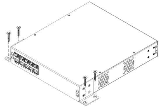
- Choose the appropriate screws that are compatible with the device and the surface you're mounting it to. If mounting to drywall, choose the appropriate drywall anchors. Screws and anchors are not provided.
-
Mount the device using all 4 holes on the mounting bracket (fig. 3).
FIG. 3: Mounting the device to the wall/ceiling mounting
Half-Width Rack Mount Installation (single unit)#
Caution
It is recommended to have two people install the device in an equipment rack. One person holds the device while the other person installs the rack screws.
Caution
When mounting multiple units vertically in a rack, it is necessary to provide adequate airflow by leaving a space between the lighting controllers.
Note
The hardware devices shown in these instructions are meant for guidance purposes and may not accurately represent the specific device or environment you're installing into.
Perform the following steps to install the device in a half-width equipment rack:
- Review all cautions and warnings to ensure safe installation practices are followed.
-
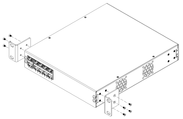
Attach the rack/wall mounting brackets to both sides of the device using the provided M3 screws, and ensure that the rack mounting holes are facing the front of the device (fig. 4).
FIG. 4: Attaching the rack/wall mounting brackets
-
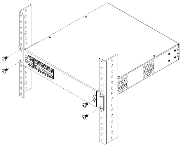
Position the device at the proper rack unit in the half-width equipment rack and install the rack screws (fig. 5). Ensure they are sufficiently tight.
FIG. 5: Mounting to the equipment rack
Rack Mount Installation (single unit)#
Caution
It is recommended to have two people install the device in an equipment rack. One person holds the device while the other person installs the rack screws.
Caution
When mounting multiple units vertically in a rack, it is necessary to provide adequate airflow by leaving a space between the lighting controllers.
Note
The hardware devices shown in these instructions are meant for guidance purposes and may not accurately represent the specific device or environment you're installing into.
Note
This installation requires additional hardware found in the XS-KIT-LB package (sold separately).
Perform the following steps to install the device in a half-width equipment rack:
- Review all cautions and warnings to ensure safe installation practices are followed.
-
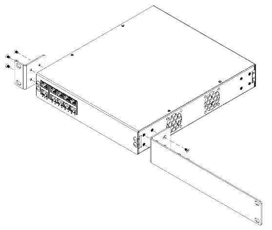
Attach the rack/wall mounting (short) bracket to one side of the device, and the rack mounting (long) bracket to the other side of the device using the provided M3 screws, and ensure that the rack mounting holes are facing the front of the device (fig. 6).
FIG. 6: Attaching the rack mounting brackets
-
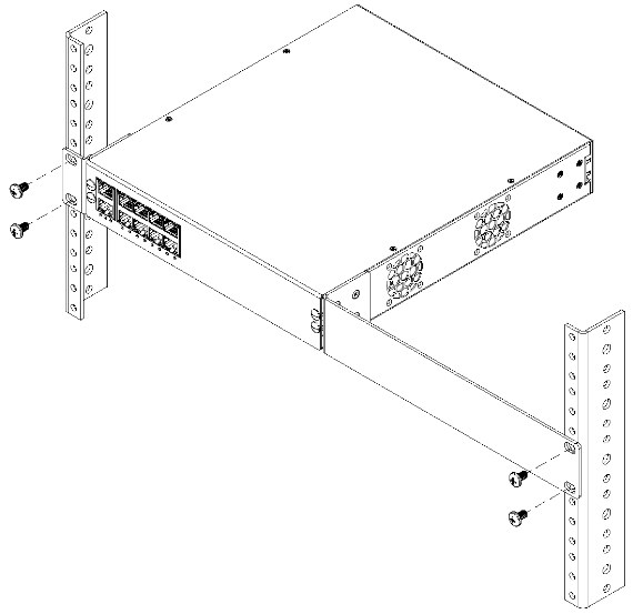
Position the device at the proper rack unit in the equipment rack and install the rack screws (fig. 7). Ensure they are sufficiently tight.
FIG. 7: Mounting to the equipment rack
Rack Mount Installation (two units)#
Caution
It is recommended to have two people install the device in an equipment rack. One person holds the device while the other person installs the rack screws.
Caution
When mounting multiple units vertically in a rack, it is necessary to provide adequate airflow by leaving a space between the lighting controllers.
Note
The hardware devices shown in these instructions are meant for guidance purposes and may not accurately represent the specific device or environment you're installing into.
Perform the following steps to install the device in an equipment rack:
- Review all cautions and warnings to ensure safe installation practices are followed.
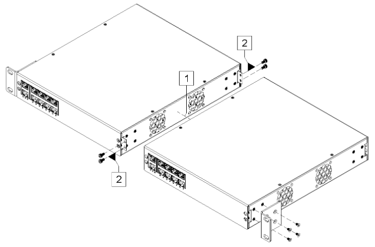
- Unpack the mounting hardware from both devices. You should have 2 rack mounting brackets and 2 coupling brackets total.
-
Attach the rack/wall mounting bracket to the left side of the left device and ensure that the rack mounting holes are facing the front of the device. Attach the coupling brackets to the right side of the right device, front and rear (fig. 8). Make sure to use the provided M3 screws.
FIG. 8: Left switch preparation
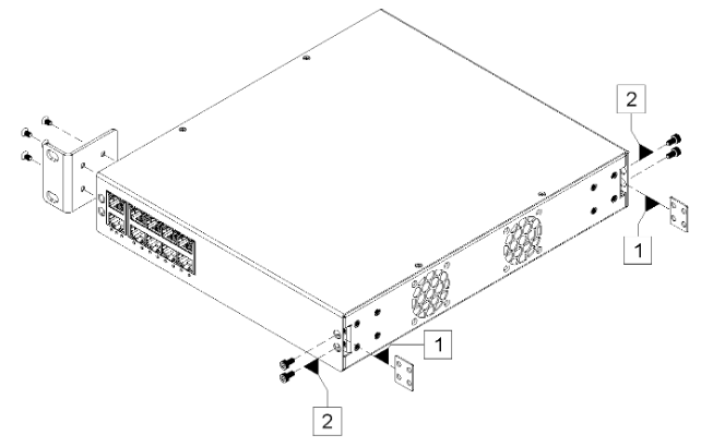
Note
Ensure that you install the coupling brackets behind the front and rear plates, rather than in front of them.
-
Attach the rack/wall mounting bracket to the right side of the right device and ensure that the rack mounting holes are facing the front of the device. Attach the right device to the left device using the coupling brackets (fig. 9). Make sure to use the provided M3 screws.
FIG. 9: Right device coupling
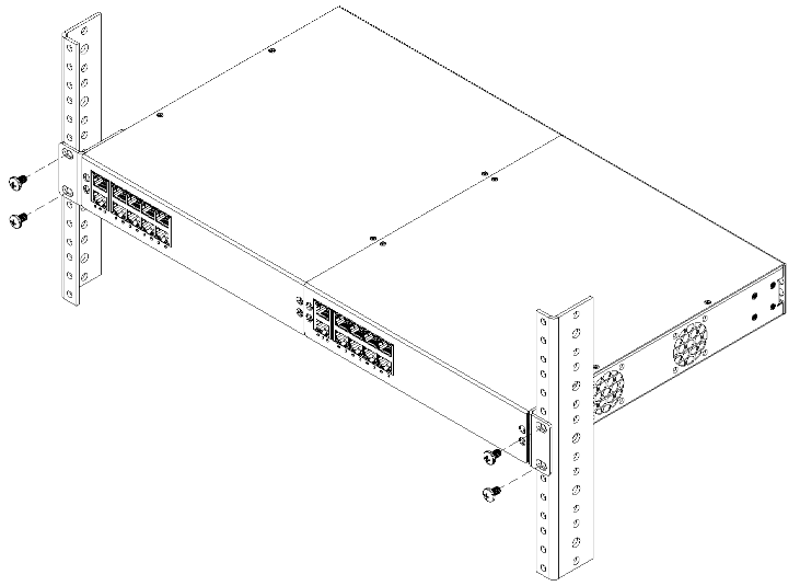
-
Position the device at the proper rack unit in the equipment rack and install the rack screws (fig. 10). Ensure they are sufficiently tight.
FIG. 10: Mounting to the equipment rack
Initial Setup#
Please review the following warnings before attempting to provide power to the device:
Danger
Do not connect the device to an external power supply before installing. Failure to observe this warning may result in electrical shock or death.
Danger
When connecting a device to power, it is important to properly secure wires in screw terminals to prevent the risk of electrical shock or fire. Failure to do so could result in damage to the equipment, injury, or death.
Danger
Always use the proper gauge wire for the external power supply being used. Using an incorrect gauge wire can result in overheating, electrical fires, or other dangerous situations.
Danger
Do not connect a power supply that exceeds the voltage specifications of the device. Always check the voltage rating of the power supply before connecting and ensure that the voltage output of the power supply matches the specified requirements. Failure to follow these guidelines may result in damage to the device, injury to the user, or both.
Caution
Ensure that the unit does not overload the power supply. Add the maximum power consumption of all the devices connected to the unit, and compare that total with the rated wattage of the power supply.
Note
An external 48VDC to 57VDC power supply is needed to power the device.
Veuillez examiner attentivement les avertissements suivants avant de tenter de fournir de l'alimentation à l'appareil :
Danger
Ne connectez pas l'appareil à une source d'alimentation externe avant l'installation. Ne pas respecter cet avertissement peut entraîner un choc électrique ou la mort.
Danger
Lors de la connexion d'un appareil à une source d'alimentation, il est important de fixer correctement les fils dans les bornes à vis afin de prévenir les risques de choc électrique ou d'incendie. Ne pas le faire pourrait entraîner des dommages matériels, des blessures ou la mort.
Danger
Utilisez toujours le calibre de fil approprié pour l'alimentation externe utilisée. L'utilisation d'un calibre de fil incorrect peut entraîner une surchauffe, des incendies électriques ou d'autres situations dangereuses.
Danger
Ne connectez pas une alimentation électrique dont les spécifications de tension dépassent celles de l'appareil. Vérifiez toujours la tension nominale de l'alimentation avant de procéder à la connexion et assurez-vous que la tension de sortie de l'alimentation correspond aux exigences spécifiées. Ne pas suivre ces directives peut entraîner des dommages à l'appareil, des blessures pour l'utilisateur, voire les deux.
Attention
Assurez-vous que l'unité ne surcharge pas l'alimentation électrique. Additionnez la consommation d'énergie maximale de tous les appareils connectés à l'unité et comparez ce total à la puissance nominale de l'alimentation électrique.
Remarque
Une alimentation externe de 48VCC à 57VCC est nécessaire pour alimenter l'appareil.
Necessary Parts#
Review the following list to ensure all necessary parts are available:
- XS-108H Lighting Controller
- 48V-57V DC Power Supply
- One or more X-PoE Powered Devices (PDs)
-
One or more LED Lighting Loads
Note
Supported lighting loads must have a current rating between 100mA - 1,200mA, with a forward voltage betweem 24V - 57V.
-
Access to an IP based network with DHCP server
Note
For small installations, the IP based network can be supplied with a standard home router.
Network Configuration#
Perform the following steps to ensure the network is set up and has a working DHCP server:
Note
Having access to the DHCP allocation table is not necessary but makes the setup easier.
- Make sure the DHCP network is NAT’ed and has an isolated subnet (192.168.1.x / subnet 255.255.255.0 as an example). This step may not be necessary when using a home router.
- Make sure the network has access to the internet. If using a home router, connect the WAN port to the Internet Modem.
Powering The Device#
Perform the following steps to properly provide power to the device:
- Ensure that the power supply is turned off and that there are no connections on the front panel before beginning the installation process.
- Remove the input connector on the device. Connect the supply wires to the input connector, ensuring that the positive and negative wires are correctly aligned.
- Secure the connection by tightening the screws on the input connector.
- Verify that the power supply is switched off and then connect the input connector to the device.
- Double-check that the connection is secure and that the wires are not exposed.
- Switch on the power supply and verify the power and system LEDs are both green. This may require several minutes.
For more information on how to interpret the power and system LEDs, refer to the front and rear panel descriptions.
Caution
When disconnecting the device, ensure that the power supply is turned off before removing the power connector.
Attention
Lorsque vous débranchez l'appareil, assurez-vous que l'alimentation est éteinte avant de retirer le connecteur d'alimentation.
Device Configuration#
Perform the following steps to configure the device:
- Ensure the device has power and plug in the network feed into the Ethernet uplink port on the device. Once the device is powered on and connected to the network, it will automatically obtain an IP address from the DHCP server.
-
Open a web browser on a computer or mobile device that is connected to the same network as the device. In the address bar of the web browser, type in “XPoE-” followed by the full mac address of the device, followed by “.local”. This should bring up the login screen for the device. (Example: for MAC Address: “AB:CD:EF:12:34:56” type “http://XPoE-abcdef123456.local”).

Note
The mac address can be found on the device’s packaging or the device itself.

Alternatively, use a network scanning tool to locate the .local or IP address. Follow this guide for additional instructions.
-
Enter the login credentials for the device. If this device has not been configured, the default username and password are:
- Username: xpoeclient
- Password: xpoepass
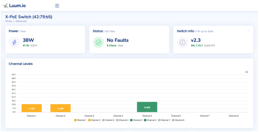
-
On the home screen, high level power data, controller status, and controller information are displayed, along with a graph indicating channel levels.
Firmware Update#
Perform the following steps to ensure the device is on the latest firmware version:
-
Navigate to the configuration settings.
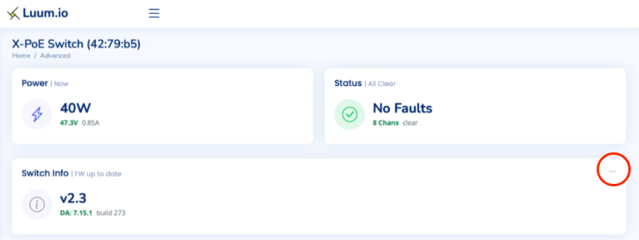
-
Select "General" and drop down "Firmware Update".

-
Select "Update to Latest".
Note
The automatic "Update to Latest" and "Update to Beta" options are only available on firmware version 4.8 or later. If the device is on an earlier firmware version, an update file will need to be provided.
Channel Configuration#
Note
IEEE PoE loads should be automatically detected and negotiate the correct power.
Note
Unconfigured X-PoE loads will have a maximum channel power output of 20%.
Perform the following steps to configure the channels:
- Connect the LED light to the PD. Then connect the PD to any of the ports on the X-PoE Switch. Ensure that the cable is securely connected on both ends. The light should turn on within 10 seconds and appear in the UI.
- If the load is a standard IEEE PD, the device will automatically detect it as such and provide the correct power.
- If the load is a standard X-PoE load, the device will automatically detect it as such the load will be operational.
- If the load is a custom X-PoE load, the device will automatically detect it as such and set the maximum port output to 20%.
-
Log in to the switch's web interface and navigate to the configuration settings for the port to make any necessary adjustments.
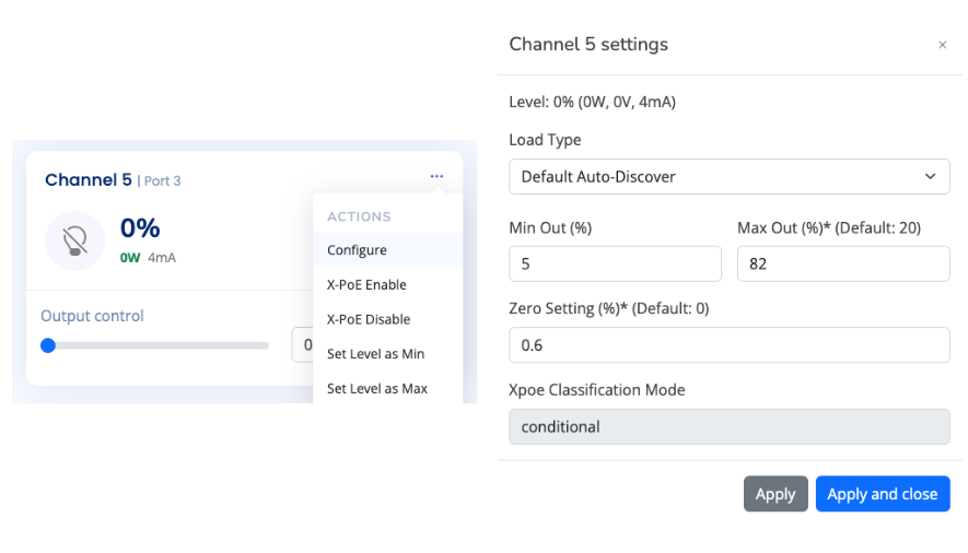
- The load type will be automatically detected. If a custom load is detected, the minimum and maximum levels need to be set.
-
It is best practice to assign load types to all X-PoE channels. These are the default load types that should be used for applying to channels:
Default X-PoE Load Types 300mA Constant Current Provides 300mA of current at 100% 400mA Constant Current Provides 400mA of current at 100% 500mA Constant Current Provides 500mA of current at 100% 600mA Constant Current Provides 600mA of current at 100% 800mA Constant Current Provides 800mA of current at 100% 900mA Constant Current Provides 900mA of current at 100% 1,000mA Constant Current Provides 1,000mA of current at 100% 1,200mA Constant Current Provides 1,200mA of current at 100% 24V Constant Voltage Channel automatically increases current until 24V is reached 36V Constant Voltage Channel automatically increases current until 36V is reached 48V Constant Voltage Channel automatically increases current until 48V is reached Switched-Full Power Provides maximum amount of current at 100%, no dimming Aggregate-Full Power ⚠️ Controls both channels of a port for when more power is needed Aggregate-Switched-Full Power ⚠️ Controls both channels of a port for when more power is needed, no dimming Default IEEE Load Types IEEE Switched Allows switching of an IEEE load Aggregate Loads ⚠️
Aggregate load types must be used with an aggregate XPD.
-
Ensure the light is controllable through the Web UI by moving the slider representing the light.
Custom Loads#
To maximize the dimming performance of individual lighting loads, custom load types can be created. Perform the following steps to configure custom loads:
Note
The custom loads feature is only available on firmware version 4.8 or later.
-
Scroll down on the X-PoE home page until the custom load types table is displayed.

-
Select "Create Load Type". This will open up the new load type menu.

-
Enter the properties for the new load type.
- Name: Provide a descriptive name for the load type.
- Max Out: Set the maximum output level for the load (e.g., 100).
- Min Out: Set the minimum output level for the load (e.g., 1).
- Zero Setting: Define the zero setting for the load, which is the level at which the load is considered off.
-
Advanced Options:

- Color Temp: If applicable, specify the color temperature associated with the load.
- Switched: Toggle this option if the load is switched (i.e., it operates in an on/off manner rather than being dimmable).
- Aggregate: Toggle this option if the load type should aggregate power from both of the X-PoE channels on a port.
- X-PoE Class Mode: Select "Never" if the load should enable automatically, "User" if it should not.
-
After entering the necessary details, click "Save" to create the custom load type. The new load type will now appear in the custom load types table, where you can view and manage it as needed.
Once a custom load type is created, you can assign it to specific channels within the channel configuration settings to optimize performance based on the defined properties.
Note
Custom loads cannot be edited.
Power On Settings#
Perform the following steps to specify what will happen to each X-PoE channel when the device powers on:
Note
The custom loads feature is only available on firmware version 5.1 or later.
-
Navigate to the configuration settings. Select "Channel Settings" and drop down "Power On Settings".

-
Configure the "Power On Setting" for each channel. The options are:
- "On": The channel will turn on to 100% when the X-PoE switch turns on. This is the default option.
- "Previous": The channel will turn on to the previously recorded level when the X-PoE switch turns on.
- "Off": The channel will remain off when the X-PoE switch turns on.
-
After configuring the channels, click "Save Changes" to apply the settings. The power on configuration will take effect immediately.
Programming Override#
Perform the following steps to configure the programming override input:
Note
The programming override configuration feature is only available on firmware version 4.8 or later.
-
Navigate to the configuration settings. Select "Channel Settings" and drop down "Emergency Override Settings".

-
Configure the "Activation Setting".
- Activate on Close: The override is engaged when the input circuit is closed.
- Activate on Open: The override is engaged when the input circuit is opened.
-
Use the "Emergency Level" fields to set the desired output percentage for each channel when the override is active (e.g., setting a channel to 100% will output full power during the override).
-
After configuring the settings, click "Save changes" to apply them. The override configuration will take effect immediately.
-
Test the configuration by using the "Emergency Test" toggle.
Note
When connecting multiple X-PoE lighting controllers to the same programming override bus, it is critical that the override input polarity is consistent across all controllers.
Operation
-
Engaging the Override:
- The override can be engaged manually by manipulating the external circuit connected to the "Programming Override Input" on the rear panel. Based on your configuration (Activate on Close/Open), the override will force all connected lighting loads to operate according to the pre-set emergency levels.
-
Disengaging the Override:
- The override will automatically disengage if the external circuit remains in the opposite state for more than 5 seconds (e.g., if configured to "Activate on Close," the override will disengage when the circuit is open for more than 5 seconds). Once disengaged, the system will revert to its previous operation mode, restoring normal control over the connected loads.
-
Indicator Lights:
- The front panel's System Status LED will flash red when the Programming Override is engaged, providing a visual indication that the system is in emergency mode.
System Configuration#
At this point, the X-PoE lighting controller can be controlled from the UI, and it's API can be integrated into various control systems. If you are using a Luum.io X-PoE controls system, continue on to the Programming Guide
Related Information#
Package And Device Labels#

Note
The package and device labels contain important information relevant to configuring the device. This information may be needed when contacting technical support.
Basic Troubleshooting#
Perform the following steps for basic troubleshooting of the device:
- Verify the initial install process. See the installation section.
- Verify the initial setup process. See the initial setup section.
- Verify the power and status LEDs are both solid green. See the front panel and rear panel sections.
- Verify the network connection and ensure that the Ethernet cable is securely plugged into both the device and the network uplink port. See the front panel section.
- Restart the device. See the button operation section.
- Factory reset the device. See the button operation section.
If both the power and status LEDs are still not solid green, continue to troubleshoot based on the color of the front status indicator and the rear power indicator.
Port Troubleshooting#
Use the following table to troubleshoot specific issues with the device based on the port status indicators:
| TROUBLESHOOTING TABLE | ||
|---|---|---|
| Power LED is OFF | The device is not receiving power | 1. With the power supply off, unplug the power connector. Confirm all conductors are secure and tight in the power connector. 2. Confirm the power connector is attached firmly to the switch. Use the locking screws to secure. Turn the power supply back on. 3. If the power LED is still off, confirm the power supply is outputting the correct voltage with a digital multimeter. |
| Power LED is RED | The polarity is reversed from the power supply | 1. With the power supply off, unplug the power connector. Reverse the + and - wires in the power connector. Confirm all conductors are secure and tight in the power connector. 2. Confirm the power connector is attached firmly to the switch. Use the locking screws to secure. Turn the power supply back on. |
| Power LED is GREEN, Status LED is RED or OFF | A malfunction has been detected in the system | 1. Restart the device. If that fails to turn the status LED green, factory reset the device (see “Button Descriptions” on page 6). 2. If both restart and reset fail, contact customer support. |
| Port Status LED is RED or OFF, Port is set to >0% | An error has been detected on the port | 1. Confirm the cable is properly connected to the device port and PD. Confirm the correct Ethernet cable type is used. Validate the terminations using a cable tester. 2. If possible, try connecting the PD to a different port on the device, or try a different PD. This will help determine if the problem is with the port or the PD. 3. Confirm the port configuration settings and check the “Advanced Debug Info” section of the web UI for any errors. |
Fault List#
Use the following table to troubleshoot specific issues based on the events in the PSE Events Timeline located towards the bottom of the X-PoE UI:
| Fault Type | Fault Name(s) | Description |
|---|---|---|
| DC Disconnect | DISCONNECT_PCUT_FAULT |
Occurs when an IEEE load disconnects. For X-PoE loads, disconnection is monitored using software and won’t trigger a PSE fault. X-PoE cable disconnect will not be detected at low load levels. |
| Short Circuit | PORT1_ILIM_FAULT |
Triggered when a channel experiences a short circuit. For IEEE loads, this shows as a short circuit fault; for XPoE, the system monitors current directly to detect faults without a PSE trigger. |
| Overdraw (I-Limit) | ILIM_START_FAULT_COR, PORT1_ILIM_FAULT |
If current is overdrawn without a hard short, an I-Limit fault occurs. This can happen for IEEE loads if the load exceeds startup inrush current requirements. |
| PCUT Fault | PORT34_PCUT_FAULT_4P, PORT12_PCUT_FAULT_4P |
An IEEE-only fault that occurs when a load exceeds its power class. This is typically hard to trigger without a load that surpasses its class rating. |
| Input Voltage Low Warning | VDD_UVLO_WARN |
A warning that the input voltage to the switch is dipping. This warning is expected once at boot but indicates voltage instability if seen otherwise. |
| Input Voltage Low Failure | VDD_UVLO_FAIL |
Indicates that the input voltage to the switch has dipped so low that the PSE cannot operate. This fault is critical and requires immediate attention. |
| Over Temperature | OVER_TEMP |
A high-temperature fault occurs if the controller exceeds safe operating temperatures. This fault should not occur under normal conditions if fans are operating correctly. |
Note
"PORT#" refers to the channel number, not the physical port number.
Technical Support#
If you experience any issues during installation or operation of this product, please contact our technical support team for assistance. Our technical support team is available via email at support@luum.io. Please provide a detailed description of the issue you are experiencing, including any error messages or other relevant information.
Warranty Information#
All Luum.io lighting products and controls come with a 5-year parts warranty. We warrant that our products will be free from defects in material and workmanship for a 5-year period from the date of purchase. Defective products under warranty will be replaced with an equal or higher quality product.
If you experience any issues with your product during the warranty period, we will repair or replace it at no charge to you. To initiate a warranty claim, please contact our customer service team at support@luum.io. For more information about our warranty policy, or for additional support options, please visit our website at www.luum.io.
Contacts#
Luum.io Headquarters
625 Kenmoor Ave STE 350
PMB 51933
Grand Rapids, MI. 49546
Phone: +1 (313) 314-3617
Document Feedback#
While we have taken great care to ensure the accuracy and completeness of this document, we welcome your feedback and suggestions to further improve it. If you notice any errors or omissions or feel that a topic could benefit from further explanation, please let us know by emailing your feedback to support@luum.io. Your input is valuable to us and will help us enhance the quality and usefulness of our documentation.
Revision History#
| HISTORY TABLE | ||
|---|---|---|
| 3/22/2023 | A | Initial XS-100 Series install guide release |
| 6/27/2023 | B | Port to docs.luum.io |
Disclaimer#
All rights, title, and interest in and to this manual, including without limitation all copyright, trademark, patent, trade secret, and other proprietary rights, belong solely and exclusively to Luum.io and/or its licensors. This manual is provided solely for the purpose of assisting in the installation and operation of the device, and no license or other rights are granted or implied hereby. No part of this manual may be reproduced, distributed, or transmitted in any form or by any means, including photocopying, recording, or other electronic or mechanical methods, without the prior written permission of Luum.io. The contents of this manual are subject to change without notice. The information contained herein is provided on an 'as is' basis and is for informational purposes only. Luum.io makes no warranty, express or implied, as to the accuracy, completeness, or usefulness of this information, nor does it assume any legal liability or responsibility for the consequences of any errors or omissions therein. The names of actual companies and products mentioned herein may be the trademarks of their respective owners.
Compliance Information#
This device is ETL certified and compliant with the ANSI/UL standard 62368-1 for safety of audio, video, and information technology equipment. The device also contains a device with FCC ID 2ADDY-P3 IC-20256-P3, demonstrating compliance with applicable FCC regulations for electromagnetic interference.
-
Maximum 130W per port with a 57V input, see D1.2 - Output Power Range. ↩↩
-
For more information, see D1.1 - Input Power Range. ↩↩