LUUM.IO
X-PoE FIXTURE INTEGRATION GUIDE#
About This Guide#
This comprehensive guide is designed to walk you through the step-by-step process of integrating a lighting fixture with an X-PoE Powered Device (PD). By following these detailed instructions, you'll be able to successfully establish a connection between your lighting fixture and the X-PoE PD, enabling efficient power delivery and lighting control.
Power Specifications#
With X-PoE, the lighting drivers are contained within the lighting controller, so there is no need for a driver or other electronics in the light fixture. But there are some power constraints to consider. The forward voltage of the light engine must be 48V or lower, and each X-PoE port can provide a maximum of 2.3A (1.15A per channel if using a 2-channel PD):
| MAX POWER SPECIFICATIONS PER PORT | |
|---|---|
| Max Light Engine Forward Voltage | 48 V |
| Max Light Engine Amperage | 2.3A |
Several fixtures can be powered by a single X-PoE port as long as the total amperage doesn't exceed the maximum amperage rating per port. See the table below for example calculations:
| FIXTURE | WATTS | VOLTS | AMPS | COMPATIBILITY | FIXTURES PER PORT |
|---|---|---|---|---|---|
| High Power LED | 250 W | 48 V | 5.2 A | ❌ | |
| High Power LED | 110 W | 48 V | 2.3 A | ✅ | 💡 |
| High Power LED | 110 W | 36 V | 3.1 A | ❌ | |
| High Power LED | 83 W | 36 V | 2.3 A | ✅ | 💡 |
| Medium Power LED | 50 W | 48 V | 1.1 A | ✅ | 💡💡 |
| Medium Power LED | 30 W | 48 V | 0.6 A | ✅ | 💡💡💡💡 |
| Low Power LED | 15 W | 36 V | 0.4 A | ✅ | 💡💡💡💡💡💡 |
To be the most compatible with X-PoE, the light engine should have a forward voltage of 48V. However, if the forward voltage is between 24V and 48V, and the current draw is less than 2.3A, the fixture is X-PoE compatible.
PD Overview#
The PD takes the RJ45 connection from an X-PoE port and converts it to one or two separate channels, each with a pair of positive (+) and negative (-) conductors. These channels are used for powering LEDs or other compatible devices, and can be daisy-chained to extend the power delivery to additional fixtures or devices. The PD can be integrated (or not integrated) with the fixture in the following ways:
Level 1 PD Integration#
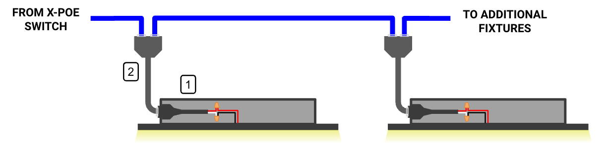
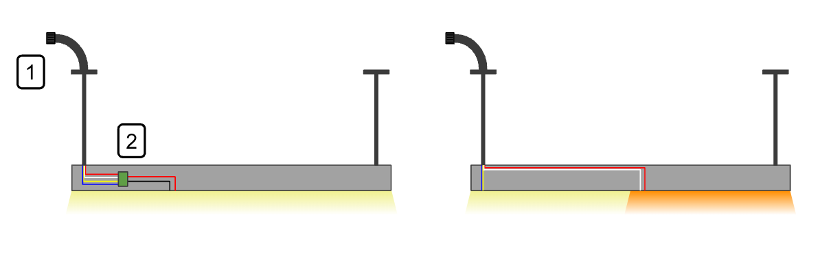
This level of integration involves little to no effort from the fixture manufacturers, and is largely done on site by the installer. The light fixture ships driverless with flying leads, and the fixture PD (XPD-T2P-G) is connected to the fixture on site. It is recommended that the PD be installed in a junction box, and the wiring connections made inside the junction box. A one or two channel PD may be used for this integration.
One Channel PD#
- When using a one channel PD, the full 2.3A of the port can be divided amongst the fixtures, and there is no specific channel wiring to take into consideration when daisy chaining. However the wiring connection at each fixture becomes a class one connection. This does not apply to the RJ45 connection to the PD.
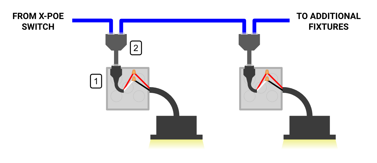
- Fixture PD (XPD-T1P-G), to be installed on site by a qualified person.
- Daisy Chain Splitter, only required for daisy chaining fixtures.
Note
All connections inside of the junction box are class one connections.
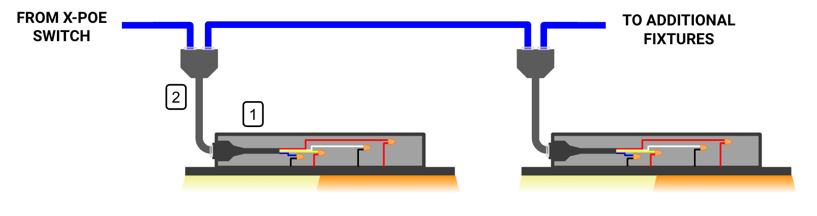
Two Channel PD#
- When using a two channel PD, the number of fixtures on a port needs to be calculated on a per channel basis, potentially leaving unused power on the port overall. For example:
- Only one 700mA fixture will fit on a channel. When using a two channel PD, this means that only two fixtures will fit on the port, even though the fixtures total 1.4A, and the total power budget for the port is 2.3A. Using a one channel PD would allow for a third fixture to be powered by the port.
- When using a two channel PD, which channel the fixture connects to need to be taken into consideration at each PD. For example:
- When daisy chaining multiple fixtures, the first fixture (or group of fixtures) will need to be wired to channel one, and the next fixture (or group of fixtures) will need to be wired to channel two.
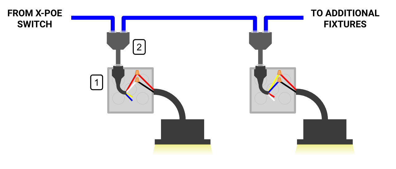
- Fixture PD (XPD-T2P-G), to be installed on site.
- Daisy Chain Splitter, only required for daisy chaining fixtures.
Note
The first fixture is wired to channel one (red/white), and the second fixture is wired to channel two (yellow/blue).
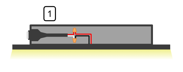
Fixture Manufacturers#
To be compatible with this level of integration, the light fixture will need to ship with no driver, and wire leads from the LED light engine coming out of the fixture.
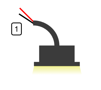
- Whip with positive and negative wire leads connecting directly to the LED light engine.
Level 2 PD Integration#
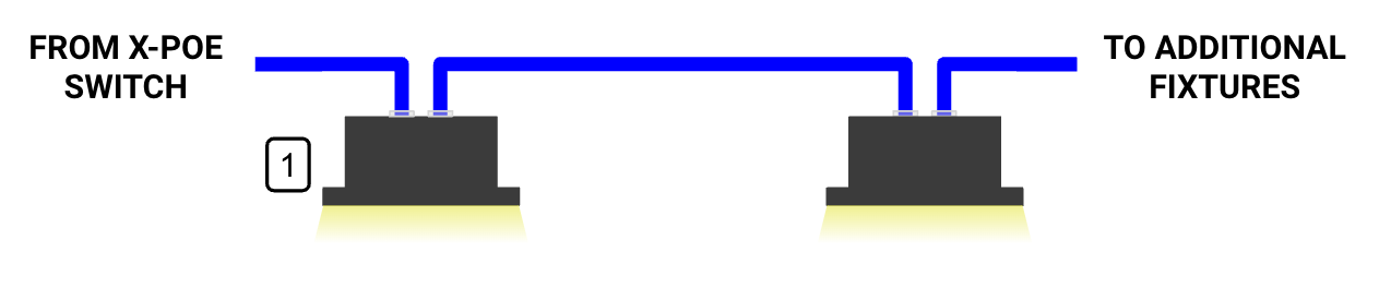
This level of integration involves minimal effort from the fixture manufacturers, but is only compatible with fixtures that have existing wiring compartments. The fixture manufacturer installs a generic, off the shelf PD before it is shipped to the site, and the fixtures arrive ready to be connected to the X-PoE ethernet wiring. A one or two channel PD may be used for this integration.
One Channel PD#
- Unless the fixture has multiple light engines for color tuning or directional lighting, a one channel PD will be used. The PD will be installed and wired to the light engine before being shipped to the site.
- Fixture with PD (XPD-T1P-G) installed from manufacturer.
- Daisy Chain Splitter, only required for daisy chaining fixtures.
Note
Because the wiring connection happens at the manufacturer, an electrician or other qualified person is not required to install these fixtures.
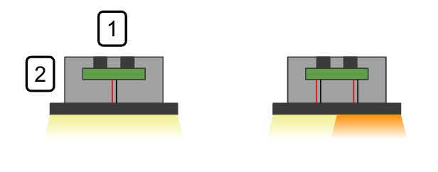
Two Channel PD#
- The two channel PD is only used with fixtures that have multiple light engines for color tuning or directional lighting. The PD will be installed and wired to the light engine before being shipped to the site.
- Fixture with PD (XPD-T2P-G) installed from manufacturer.
- Daisy Chain Splitter, only required for daisy chaining fixtures.
Note
The two channels are used for color tuning or other similar purposes. Not for individual control.
Fixture Manufacturers#
To be compatible with this level of integration, the light fixture will need to have a wiring compartment, and ship with a fixture PD (XPD-T1P-G or XPD-T2P-G) already installed.
Level 3 PD Integration#
This level of integration involves significant effort from the fixture manufacturer. The light fixture ships with a whip terminated to a connector. Once on site, the fixture is ready to be plugged into a PD with a mating connector. No junction box or wiring enclosure is needed. A two channel PD is used for this integration.
Two Channel PD With Connector#
- The two channel PD with connector is used with fixtures with a single light engine, as well as fixtures that have multiple light engines for color tuning or directional lighting.
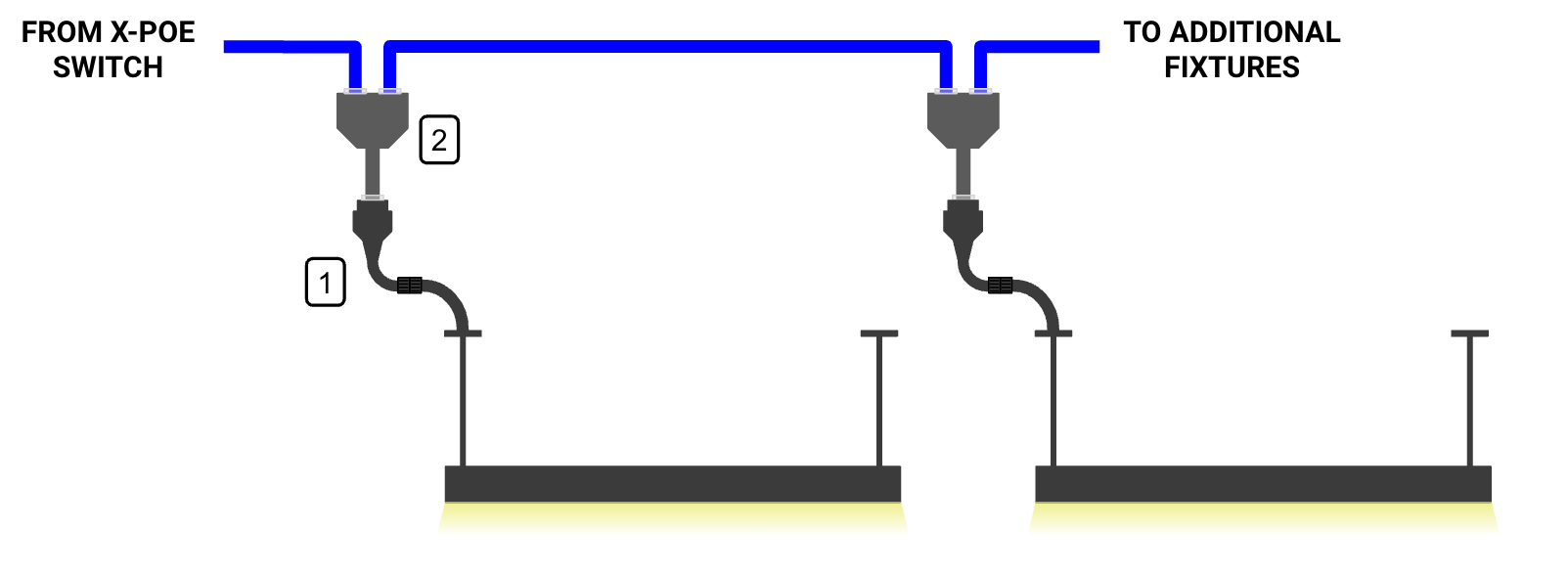
- Fixture with PD (XPD-T2P-P), to be installed on site.
- Daisy Chain Splitter, only required for daisy chaining fixtures.
Note
Although this level of integration can be accomplished with any type of fixture, it is best for fixtures like pendant mount and linear fixture types.
Fixture Manufacturers#
To be compatible with this level of integration, the light fixture will need to have a wire whip terminated with a connector. Fixtures with a single light engine will need to incorporate a simple aggregation PCB or circuit.
- Wire whip with 4-pin connector.
- Aggregation circuit (only necessary for fixtures with a single light engine).
Level 4 PD Integration#
This level of integration involves the most effort from the fixture manufacturer. However, it is the most optimized method for integrating fixtures with the X-PoE system. The light fixture ships with an integrated PD circuit, and has RJ45 port(s) ready to be connected to the X-PoE ethernet wiring. Both channels are available to be used within the light fixture.
X-PoE Light Fixture#
- The PD is integrated into the light fixture. Both channels are available for fixtures with a single light engine, as well as fixtures that have multiple light engines for color tuning or directional lighting.
- X-PoE compatible light fixture with integrated PD.
Note
A daisy chain splitter will be necessary of the fixture can be daisy chained and the manufacturer only has a single port on the fixture.
Fixture Manufacturers#
To be compatible with this level of integration, the light fixture will need to have a PD circuit integrated inside the fixture, as well as RJ45 port(s) exposed as connections to the fixture. Both channels are to be used for fixtures with a single light engine, as well as fixtures that have multiple light engines for color tuning or directional lighting.
- RJ45 port(s) exposed as connections to the fixture.
- Integrated PD circuit.
Level 0 PD Integration#
This level of integration involves no effort from the fixture manufacturer, and is reserved for LED strips. This integration is done on site by the installer, and utilizes the LED strip PD (XPD-P2H-G). A two channel PD is used for this integration.
Note
The LED strip PD (XPD-P2H-G) is not UL listed or plenum rated. It is not to be used in spaces that require those ratings.
LED Strip#
- The PD is installed near the LED strip. Both channels are available if the strip requires too much power for one channel, or if the strip has multiple LED colors.
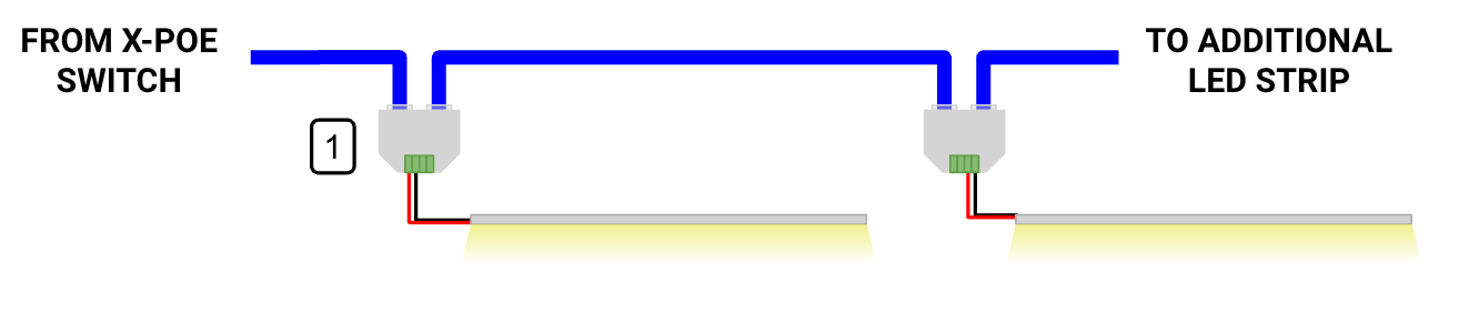
- LED Strip PD (XPD-P2H-G), to be installed on site.
Note
The second channel cannot be physically wired to the first to allow for more power. The second channel must be used separately on an additional length of LED strip.
X-PoE Class#
Apart from converting the RJ45 connection to DC outputs, PDs also feature signature resistors on each channel. These resistors play a crucial role in helping the X-PoE lighting controller identify the specific X-PoE class associated with the PD. This class information, guides the lighting controller in determining the load's power requirements and facilitates automatic configuration of the X-PoE port. For a detailed breakdown of the various X-PoE classes and their corresponding class signature resistors, please consult the table below:
| Signature Resistor Value | XPOE Class |
|---|---|
| 32k | 300mA Constant Current |
| 13k | 400mA Constant Current |
| 14k | 500mA Constant Current |
| 16k | 600mA Constant Current |
| 6k5 | 800mA Constant Current |
| 10k6 | 900mA Constant Current |
| 7k | 1000mA Constant Current |
| 8k | 1200mA Constant Current |
| 8k5 | 48V Constant Voltage |
| 9k5 | 36V Constant Voltage |
| 11k5 | 24V Constant Voltage |
| 12k5 | Manual Config - Default 100mA |
Note
The placement of the X-PoE class signature resistor is designated for channel one. In the event that the fixture's power requirement exceeds 1,200 mA, one signature resistor on each channel will be used, distributing the load evenly.
X-PoE Fixture Certification Program#
The X-PoE Certification Program is available to fixture manufactures looking to ensure the best performance and integration with the X-PoE system. The X-PoE Certification Team will test the lighting fixtures and store the optimal X-PoE settings for use during system configuration. A PD solution will be developed for the light fixture, with custom PD solutions available. The fixture will be fully X-PoE certified and showcased in a database of the best performing X-PoE fixtures available to specifiers.
To certify a light fixture for X-PoE, contact Luum.io